This DIY PIC programmer is a continuation of our tutorial. By using this USB PIC programmer, you can program microchip PIC series of 10F, 12F, 16F, 18F, 24F, 30F. This is also an EEPROM programmer as it supports 12Cxx EEPROM. The main component of this PIC microcontroller programming circuit is a PIC182550 microcontroller which controls the overall circuit. Serial port PIC programmers are the widely used PIC chip programmer Kit, but since laptops have no RS232 ports they require an USB to RS232 converter.

Recommended for you: • • Now one of the main advantages of this circuit is that it does not require any external power supply, instead it uses USB power. It generates programming voltage of 13V through voltage multipliers. Linux PIC programmer software is also available for burning. You can program micro controller like pic16f84a, pic16f877a, pic18f4550, pic16f628a etc. And make your micro controller programming easier.
Circuit diagram of PIC Chip Programmer. Hello Yaseen, thank you very much for all of these tutorials, they’ve been very useful to me. Sbornik uprazhnenij po russkomu yaziku rozentalj reshebnik. I have a question, I hope you could answer it to me: I’ve been checking many websites regarding the USB Pic Programmer, some of them say you need burn the boot and then the firmware to the 18F2550, some say you only the need the firmware.
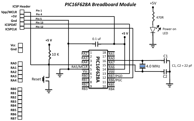
PIC16F628A Programmable Digital Timer. Another interesting feature of this project is it offers cyclic option, which means you can choose to run it in a continuous loop of ON and OFF cycles. The device can be programmed through 4 push switches. The programming menu and device status are displayed on a 16×2 character LCD. Dec 3, 2010 - The layout and the circuit diagram of the module is shown below. The module has ICSP header pins for in-circuit programming, a reset switch,.
What’s the difference between the boot and the firmware? The firmware, if i’m correct, transforms the USB signals to ICSP signals, but what’s the function of the boot? The official website (usbpicprog) says I have to burn the boot and the firmware, other sites (like this one) tell me that you only need to burn the firmware.hex, so i’m a bit confused. Could you please tell me about the boot and the firmware? Is it going to work If I burn the 18F2550 with the firmware.hex using a JDM programmer without previously burning the bootloader?

Haii,I need help I’m tying to program 16f877a (MPLab htc) for an lcd (16×2) by using this programmer,but failed(nothing displayed).I reconnect the lcd circuit again n again.but it doesn’t give any response.The programmer works for simple led blink. Also the verification some times fails,next time pass for the same program And the programmer have this problem,it turns off several times(all leds off and disconnected),after detecting PIC or after one programming,without a reason.After that i want to reconnect the usb cable and reopen the software(software connect isn’t working).Plz help me to solve this problems.
Sir, I am aged but interested in micro controllers. I want to know what is the difference in burning a program and communicating on hyper terminal. I have a developer board which have 9 pin D connector, but my PC do not have 9 pin connector.
So I used a 9 pin to USB adaptor and tried to burn my hex file to uC. But the PIC pgm or mikroProg does not recognize my board. Using hyper terminal I could communicate with micro. It gives some output text when I type some letters on the key board of my PC. Please any body help to understand some basics of PIC micro – like, what is bootloader, what is communicating on hyper terminal, what is burning using USB and what is 9 pin D connector. Haii,I need help I’m tying to program 16f877a (MPLab htc) for an lcd (16×2) by using this programmer,but failed(nothing displayed).It works fine with Proteus.I reconnect the lcd circuit again n again.but it doesn’t give any response.The programmer works for simple led blink. Also the verification some times fails,next time pass for the same program And the programmer have this problem,it turns off several times(all leds off and disconnected),after detecting PIC or after one programming,without a reason.After that i want to reconnect the usb cable and reopen the software(software connect isn’t working).Plz help me to solve this problems.
Good day sir. I am one of your website users. I have one small issue that I want to share with u.
I got a 2kva ready made inverter which works fine with my appliances. But when I tried to use it with my freezer.
It comes on and d engine starts but it doesn’t get cold even after hours.i decided to plug it to my working generator and it worked fine. Pls what could have caused it for the inverter not to make the freezer get cold and how can I go about fixing it. Your quick response will be highly appreciated sir. Dear Sirs, I have built the USB Pic Prog and I am trying to get it to work on Vista 32 bit.
Top Articles
- Grease Torrent Tpb
- Bongo 2 Keygen Generator Crack
- Download Film Anime 18 Subtitle Indonesia Fast
- Download Tiger Woods 08 Widescreen Patch Free
- Sophie Zelmani Sophie Zelmani Rar Files
- Shablon Dlya Brelka S Gos Nomerom
- Sony Vaio Recovery Disk Torrent
- Index Of Ms Visio 2010 Iso Download
- Ultimate Spiderman Game Cracked
- Building And Engineering Contracts By B S Patil Pdf Download
- Lal Kitab Book In Bengali Pdf Ebook
- Elite Volare Mag Lite Indoor Trainer Manual For Life